
请输入产品关键字:

DIN55662涂料和清漆抗压力水射流试验标准
点击次数:741 发布时间:2022-4-12
上海鼎徵仪器仪表设备有限公司 蒸汽喷射试验机满足测试规范汽车厂家:宝马、奔驰、通用、大众、福特、沃尔沃等规范(AA-0136、DIN 55662、ISO16925,DBL 7381,GM9531P、PV1503、VOLVO STD 423-0015,VOLVO VCS 1029 54719、FLTM BO 160-04、MS210-07,PSA D23 5376,Renault D25 2018/-A-2001 ,GMW16745-2012方法B,TPJLR-52.561-2009)
1 Scope 上海鼎徵仪器仪表设备有限公司
This International Standard specifies a test method for the assessment of the resistance of coatings to
pressure water-jetting. The test method simulates the effects pressure water-jetting has on a coating.
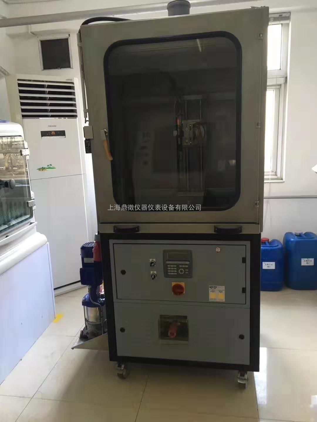
5 Apparatus and materials
Ordinary laboratory apparatus, together with the following:
5.1 Pressure water-jet, consisting of a high-pressure pump and a nozzle.
A high-pressure pump conveys the water from a storage bin. To avoid influences from variations in
pressure, it is necessary that the pressure and the volumetric flow rate be adjustable at the nozzle
described below.
The water temperature shall be adjustable to ± 2 °C.
The temperature shall be adjusted in accordance with Annex A. Necessary safety devices on the pressure
side of the unit, as e.g. pressure relief valve and by-pass valve, shall exist. If the jetting is unsteady, a flow
calming section may be installed in front of the nozzle. A pulsation of the water jet at the opening of the
pump is inadmissible. In order to reach a reproducible result, the nozzle shall be solidly mechanically
fixed and the test specimen shall be secured against slipping. For the adjustment of the volumetric flow
rate, a nozzle with a jet angle of 25° and a volumetric flow rate of 6 l/min at 2 MPa (20 bar) is required
(see Annex A).
The following technical data should be attainable:
— volumetric flow rate: 8 l/min to 14 l/min
— pressure: 4 MPa (40 bar) to 13 MPa (130 bar)
— temperature: 20 °C to 80 °C
— jetting time: 10 s to 300 s

Figure 1 shows the schematic construction of a pressure water-jet apparatus which is specially built for these tests.
Key
1 flow calming section
2 high-pressure valve, height adjustable
3 test specimen
4 clamping element
5 feed tank
6 floating valve with filter
7 water shortage safeguard
8 heating
9 base frame, moveable
10 temperature sensor
11 high-pressure pump
12 by-pass valve
13 pressure relief valve
14 pressure transmitter
8.1 Introducing the cut or the scribe 上海鼎徵仪器仪表设备有限公司
Make sure that the test specimen is securely fastened when introducing the cut or the scribe.
Introduce both of the cuts or scribes vertically through the coating into the substrate using the cutting
or scribing tool, as shown in Figure 2. The depth of the cut or scribe into the substrate should be as
minimal as possible. The length of the first cut or scribe shall be at least 100 mm, if the geometry of the
part allows that. At an angle, introduce a second cut or scribe with a minimum length of 20 mm. The
cuts or scribes shall be introduced straight-line at an angle of approximately 30°. An automatic cutting
or scribing device may be used. Residues of the coating shall be removed from the cut or scribe.
NOTE The depth of the cut or scribe into the substrate influences the result.
The cutting or scribing tools should be checked regularly and replaced if necessary.
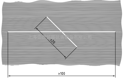
Figure 2 — Introducing the cuts or scribes (St Andrew’s cross)
8.2 Testing
After inserting the test specimen into the apparatus (e.g. using a spacer block), calibrate the space
between test specimen and nozzle.
Operate the pressure water-jetting apparatus at room temperature.
Three test methods (A, B, or C – see Table 1) are preferred as well as three possible scribing tools (C, L, or
S – see 5.3). The test method to be applied, the scribing or cutting tool to be used, and the water pressure
shall be agreed.
Table 1 — Test methods 上海鼎徵仪器仪表设备有限公司
| Test method | Water Temperature ℃ | Impact angle | Space between nozzle and sample (mm) | Flow rate (L/min) | Duration of jetting |
| A | 60±2 | 90±2 | 100±1 | 11.3±0.2 | 30±1 |
| B | 60±2 | 90±2 | 100±1 | 11.3±0.2 | 60±1 |
| C | 60±2 | 90±2 | 100±1 | 11.3±0.2 | 60±1 |
For jetting, deionized water should be used.
When using automatic and manual devices, fasten the test specimen so that the water jet impacts as
shown in Figure 3. The jet impacts in the middle above the point of intersection onto the longer one of both cuts/scribes.
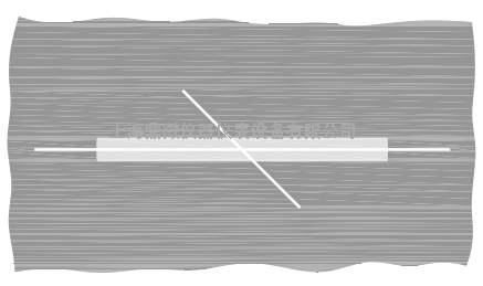
Figure 3 — Jetting area
9 Evaluation
9.1 General
Damage is recognizable when the coating loosens or flakes, regardless of which coat sustains the damage.
9.2 Evaluation with pictures to compare
Carry out the evaluation visually, comparing the specimen with the pictures.
In the course of the visual evaluation, a characteristic value is laid down by comparing with the
illustrations in Figures 4 to 9. A characteristic value between 1 and 5 results, depending on the degree
of damage. No damage corresponds to the characteristic value 0. In addition to the evaluation, if
applicable, the attribution of the separation from the main separation level or to the respective film
shall be indicated.
The result of the visual assessment is indicated in dependence of the applied method, for example:
— method A: characteristic value A;
— method B: characteristic value B;
— method C: characteristic value C.
NOTE In addition, by measuring the areas of flaking (maximum width, in millimetres, or area, in square
millimetres), the overall damage can be evaluated. The overall damage is calculated by summing up all damaged
areas of the test specimen. Even the smallest areas of flaking are measured and calculated, and all areas added to
the overall damage. 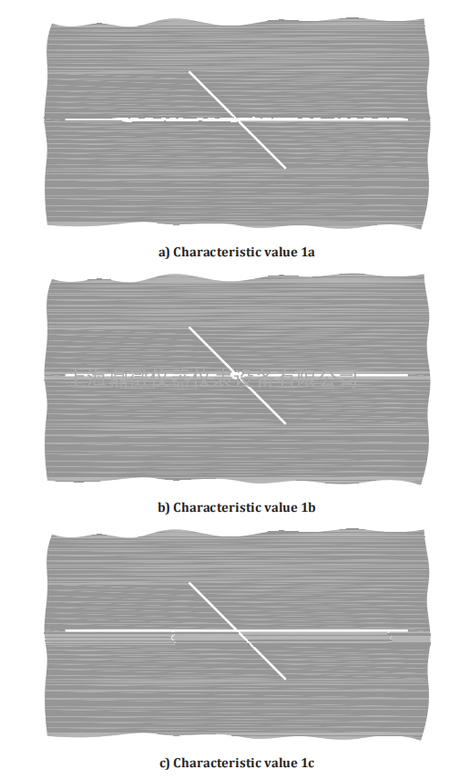
Figure 5 — Characteristic value 1 for pressure water-jet damage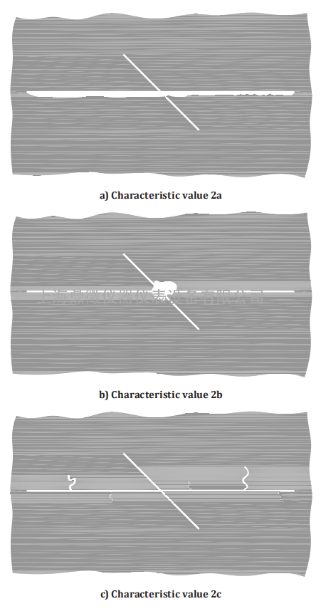
Figure 6 — Characteristic value 2 for pressure water-jet damage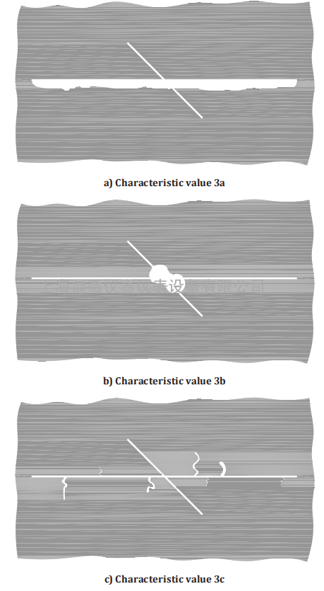
Figure 7 — Characteristic value 3 for pressure water-jet damage
Figure 8 — Characteristic value 4 for pressure water-jet damage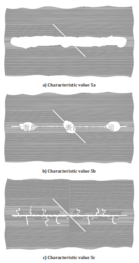
Figure 9 — Characteristic value 5 for pressure water-jet damage
Annex A
(normative)
Calibration of the test apparatus
A.1 Apparatus and materials
Ordinary laboratory apparatus, as well as the following.
A.1.1 Temperature measuring device, with sensor, capable of measuring to 0,5 °C.
A.1.2 Balance, weighing to 10 g.
A.1.3 Time measuring device (stopwatch), capable of measuring ± 0,1 s.
A.1.4 Container, for the determination of the volumetric flow rate for at least 20 l of water.
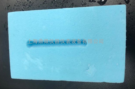
A.1.5 Plastic block, made of polystyrene rigid plastic foam.
The kind of the polystyrene rigid plastic foam shall be agreed by the interested parties.
A.1.6 Length measuring device, capable of measuring ± 0,1 mm.
A.2.4 Calibration of the water jet
The conditions for the calibration of the jetting are in accordance with method B. For the calibration of
the jetting, a stainless steel precision flat film extrusion die with a volumetric flow rate of the nozzle of
6 l/min at 2 MPa (20 bar) and a jet angle 25° is used. This nozzle is required to produce an even liquid
distribution during the entire jetting.
When using an automatic pressure-water apparatus, fasten the polystyrene rigid plastic foam in the
apparatus so that the jet cannot move the block. When using a manual apparatus, fasten the block in a
similar fixture.
After jetting, the length and the width of the impact are measured. See Figure A.1.
The mean length of the impact shall be (73 ± 5) mm and the mean width (8 ± 1) mm on average.
Figure A.1 — Measures of the washed-out areas in the polystyrene rigid plastic foam