

-
01 质量保证
核心部件均来自国外进口,从源头把控产品质量。产品从生产到出货需经历三道全检工序,严苛的质检体系,确保出厂。下单7天即可交付,急单出货2天内出货,确保交期。
-
02 企业实力
12年专注从事玻璃钢风机研发,20000平方米生产基地,年产风机设备3万台以上“万通风机”是制造,质量、服务、信誉AAA企业!获得多项国家及资质证书,行业好口碑!
-
03 服务特色
1对1服务,提供到公司测量性能、震动,提供测试报告,防范故障于未然,保障风机在状况下运转。可针对客户的特殊规格,量身定制设计,确保风机运转于率点。
-
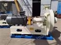
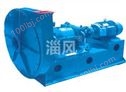
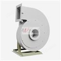
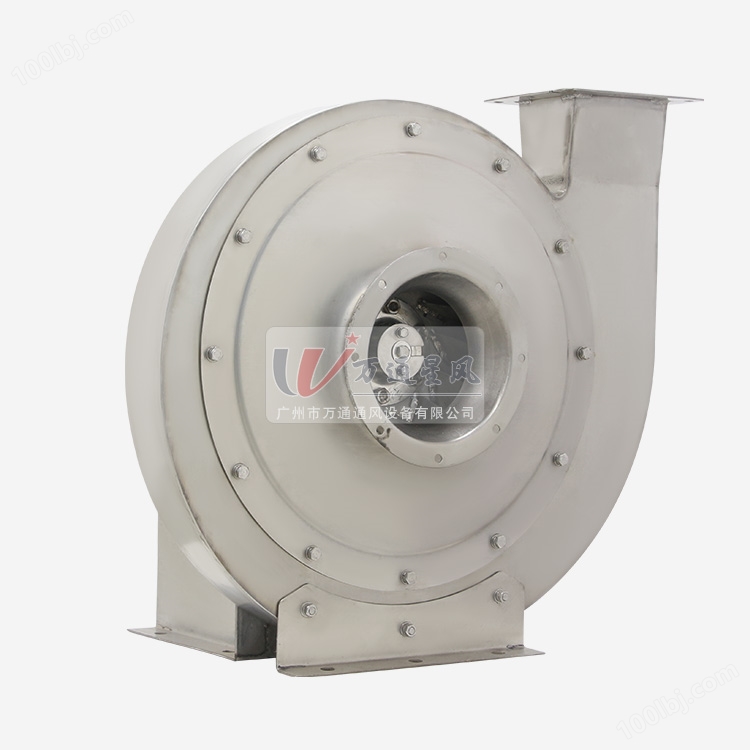
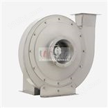
不锈钢9-19高压离心风机
9-19型高压离心式通风机一般用于锻冶炉及高压强制通风机,可广泛用于输送物料,输送空气及无腐蚀性不自然,不含粘性物质及气体。介质温度一般不超过50℃(不超过80℃)。介质中所含尘土及颗粒不大于150mg/m3。
产品型式:本厂机号有NO3.15、3.55、4、4.5、5、5.6、6.3、7.1八种。可制成右旋和左旋两种型式,叶轮顺时针旋转,称为右旋风机。以“右”表示,叶轮逆时针旋转,称为左旋风机,以“左”表示。风机的出口位置,以机壳的出风角度表示,9-19型风机NO3.15~7.1出厂时均做成多种型式,可根据使用单位要求安装成所需的位置,即出风口位置调整范围0°~225°或45°,即(0°、45°、90°、135°、180°、225°)共六种。NO7.1根据用户需求制成一种方向角度。风机的传动方式为A式(NO3.15~6.3)和D式NO7.1两种。
结构特点:本风机主要由叶轮、机壳、进风口、机架、底架、轴承箱等皮带传动而组成。叶轮:由10个后倾的机翼型叶片、曲线型前盘和平板后盘组成,并经过动平衡校正,气动性能,故运转平衡、振动小、效率高、寿命长等特点。机壳:用钢板焊成蜗型壳体。进风口:制成整体(全部模具成型),装于风机的侧面,于轴向平行的戴面为曲线形状,能使气体顺利进入叶轮,且损失较小。传动组:由主轴、轴承箱、联轴器等。主轴由优质钢制成,轴承箱整体结构,采用滚动轴承,分为水冷和油冷两种。 -
SUS 9-19 high pressure centrifugal fan
9-19 high pressure centrifugal fan is generally usedforforging furnace and high pressure forced fan, can bewidely used in conveying materials, conveying air andnon-corrosive nature, non-sticky substances and gases. The medium temperature is generally not more than 50℃ with maximum below80℃. The concentration of mediacontaining dust and particles is not more than 150mg/m3.Product type: The factory number is NO3.15, 3.55, 4, 4.5, 5, 5.6, 6.3, 7.1. It can be made into two types: right-handed and left-handed. The impeller rotates clockwise and is called a right-handed fan. Expressed as "right", the impeller rotates counterclockwise, called the left-handed fan, and is represented by "left". The outlet position of the fan is expressed by the air outlet angle of the casing. The 9-19 type fan NO3.15~7.1 is made into various types when it leaves the factory. It can be installed to the required position according to the requirements of the unit, that is, the position of the air outlet is adjusted. The range is 0°~225° or 45°, that is, (0°, 45°, 90°, 135°, 180°, 225°). NO7.1 is made into a direction angle according to user requirements. The transmission mode of the fan is A type (NO3.15~6.3) and D type NO7.1.Structural features: The fan is mainly composed of impeller, casing, air inlet, frame, chassis, bearing box and other belt drives. Impeller: It consists of 10 backward-inclined airfoil blades, curved front plate and flat rear plate. It has dynamic balance correction and aerodynamic performance, so it has the characteristics of balanced operation, small vibration, high efficiency and long service life. Housing: welded with a steel plate into a volute casing. Air inlet: made into a whole (all mold molding), installed on the side of the fan, and the axially parallel wearing surface has a curved shape, which enables the gas to smoothly enter the impeller with less loss. Transmission group: from the main shaft, bearing housing, coupling and so on. The main shaft is made of high-quality steel. The overall structure of the bearing housing is made of rolling bearings and is divided into water-cooling and oil-cooling.
| 机 号 Model(NO) | |||||
|---|---|---|---|---|---|
| 转 速 Speed(r/min) | 功 率 Power(KW) | 机座号 Poles frame size-p | 流 量 Volume(M3/h) | 全 压 Total pressure(pa) | |
| 3.15A | 2900 | 0.75-2 | Y132S-2 | 402-545 | 2223-2262 |
| 2900 | 1.1-2 | Y80M-2 | 617-832 | 2231-2017 | |
| 3.55A | 2900 | 1.5-2 | Y90S-2 | 560-760 | 2545-2590 |
| 2900 | 2.2-2 | Y90L-2 | 860-1160 | 2554-2310 | |
| 4A | 2900 | 2.2-2 | Y90L-2 | 824-1264 | 3584-3597 |
| 2900 | 3.0-2 | Y100L-2 | 1410-1704 | 3507-3253 | |
| 4.5A | 2900 | 4.0-2 | Y112M-2 | 1174-2062 | 4603-4447 |
| 2900 | 5.5-2 | Y132S-2 | 2281-2504 | 4297-4112 | |
| 5A | 2900 | 7.5-2 | Y132S-2 | 1610-2844 | 5697-5517 |
| 2900 | 11.0-2 | Y160M-2 | 3166-3488 | 5323-5080 | |
| 5.6A | 2900 | 11.0-2 | Y160M-2 | 2622-3619 | 7182-7109 |
| 2900 | 18.5-2 | Y160L-2 | 3996-4901 | 6954-6400 | |
| 6.3A | 2900 | 18.5-2 | Y160L-2 | 3220-5153 | 9149-9055 |
| 2900 | 30.0-2 | Y200L-2 | 5690-6978 | 8857-8148 | |
| 7.1D | 2900 | 37.0-2 | Y200L-2 | 4610-7376 | 1171-11596 |
| 2900 | 55.0-2 | Y250L-2 | 8144-9988 | 11340-10426 |
外形及安装尺寸示意图 Lnstallation size diagram
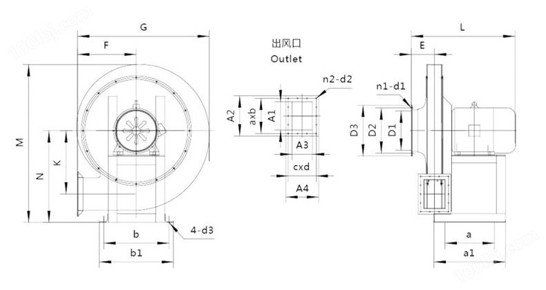
产品为人工实物测量会有一定误差,相关数据仅作参考,以收到的实物为准。 单位Unit: mm(毫米)
| 机号 | |||||||||||
|---|---|---|---|---|---|---|---|---|---|---|---|
| 进风口尺寸 Air inlet | 出风口尺寸 Vent | ||||||||||
| Model | D1 | D2 | D3 | n1-d1 | A1 | A2 | A3 | A4 | a*b | c*d | n2-d2 |
| 3.15 | 147 | 180 | 210 | 8-Φ8 | 107 | 168 | 93 | 154 | 69.5*2 | 60*2 | 8-Φ11 |
| 3.55 | 165 | 197 | 215 | 130 | 198 | 96 | 155 | 55*3 | 63*3 | 10-Φ11 | |
| 4 | 186 | 211 | 244 | 135 | 202 | 110 | 170 | 57*3 | 70*2 | 10-Φ11 | |
| 4.5 | 208 | 230 | 253 | 145 | 212 | 110 | 170 | 61*3 | 70.5*2 | 10-Φ11 | |
| 5 | 227 | 258 | 285 | 163 | 230 | 133 | 194 | 66*3 | 81*2 | 10-Φ11 | |
| 5.6 | 258 | 285 | 305 | 193 | 251 | 163 | 223 | 75*3 | 64.3*3 | 12-Φ11 | |
| 6.3 | 290 | 323 | 350 | 205 | 270 | 165 | 226 | 81*3 | 65*3 | 12-Φ11 | |
| 7.1 | 326 | 355 | 395 | 8-Φ11 | 227 | 294 | 163 | 232 | 54*5 | 69*3 | 16-Φ11 |
| 机号 | ||||||||||||
|---|---|---|---|---|---|---|---|---|---|---|---|---|
| 外形及安装尺寸 Shape and installation dimensions | ||||||||||||
| Model | G | M | L | F | N | K | E | a | b | a1 | b1 | d1 |
| 3.15 | 484 | 586 | 362 | 221 | 336 | 234 | 74 | 330 | 120 | 355 | 245 | Φ11 |
| 3.55 | 549 | 660 | 397 | 255 | 370 | 254 | 86 | 365 | 140 | 397 | 260 | |
| 4 | 620 | 700 | 466/426 | 283 | 400 | 286 | 98 | 350 | 200 | 385 | 360 | |
| 4.5 | 692 | 780 | 567/492 | 325 | 450 | 330 | 109 | 390 | 240 | 430 | 410 | |
| 5 | 763 | 880 | 706/576 | 362 | 500 | 352 | 120 | 450 | 340 | 500 | 440 | |
| 5.6 | 820 | 980 | 768/723 | 367 | 570 | 400 | 133 | 484 | 350 | 532 | 447 | |
| 6.3 | 933 | 1100 | 908/783 | 426 | 645 | 450 | 148 | 570 | 450 | 625 | 567 | |
| 7.1 | 1037 | 1230 | 870 | 460 | 690 | 508 | 170 | 600 | 480 | 710 | 570 | Φ20 |


 网站客服
网站客服